A CASE STUDY OF A TIME OF FLIGHT DIFFRACTION SYSTEM APPLIED TO DEFECT MONITORING ON LONGITUDINALLY SEAM WELDED PIPE.
AUTHOR : S. A. WEBBER, AUSTA ENERGY.
Abstract
The object of this paper is to describe the benefits of the time of flight diffraction (TOFD) ultrasonic test system when used to evaluate defects over time. The principles of the TOFD system are described along with its benefits compared to conventional A-scan systems. AUSTA Energy, having purchased a TOFD system, have employed it on an extensive survey programme of longitudinally welded pipes. Defects found by the conventional A-scan methods were further evaluated and archived using the TOFD system. One of the defects archived was retested approximately eighteen months later and the comparison of the results are shown.
Introduction
By far the most common ultrasonic method applied in the field to weld testing is the conventional A-scan system. With the advent of the PC we are now seeing some automation of conventional ultrasonics in the field whilst previously such developments were practically restricted to research laboratories or factory production lines of the original equipment suppliers. One of the emerging contenders of automated ultrasonic testing in the field is the time of flight (TOFD) ultrasonic systems. Before the higher cost of this type of system can be justified, potential users and beneficiaries have to be made aware of the benefits of the system and also educated to understand the differences between it and conventional A-scan ultrasonics.
As utilities seek to stretch their plant, frequently beyond its design life, it is becoming increasingly important to have test systems which can gather accurate information about the plants integrity. For some utilities this involves possible extensive NDT surveys looking even into areas where they had not considered in the past but as part of the plant integrity survey this has now become necessary. A common drawback of the conventional A-scan system is its inability to produce hard copy results for common evaluation or archival purposes. Another common criticism of conventional A-scan ultrasonics, especially in the case of having to monitor a defect over a number of years, has been the lack of reproducibility as the system relies so heavily on the interpretive skills of the operator. Even with the introduction of many of the modern digital conventional A-scan machines which allow all test parameters to be stored, including often the ability to store A-scans, the same problem persists. The TOFD system allows both the production of hard copy results of the image of the defect within the material and also has excellent reproducibility capabilities.
AUSTA Energy, having a number or areas where defect monitoring is required, have invested in a TOFD system. The main argument for the purchase of the TOFD was based on the need for a more reliable test system needed for the inspection of austenitic generator retaining rings. These are large items that proved impossible to monitor with the manual A-scan systems due mainly to the plethora of spurious indications resulting from the underlying geometry of these items. Having developed the TOFD system around the effective testing of generator end rings AUSTA Energy began to apply the system to weld inspection. As stated earlier AUSTA Energy have a requirement to be able to monitor defects as reliably as possible over long time spans. This requirement was paramount in an extensive programme of testing longitudinal welds in all of AUSTA Energy’s modern power stations. This programme was initiated owing to catastrophic failures having occurred in welds of similar configuration in the United States of America. It was considered that the manual ultrasonic systems would not be appropriate as they lacked the ability to provide the level of both repeatability and accuracy in defect sizing required. Both of these attributes were considered as essential to determine if defect growth had occurred between tests, some of which may be five or even ten years apart.
This paper outlines AUSTA Energy’s experience in the use of its TOFD system with particular regard to its application to longitudinally welded pipes. Also given is a description of the TOFD system and hard copy examples of TOFD scans.
Time of Flight Diffraction ultrasonic principle.
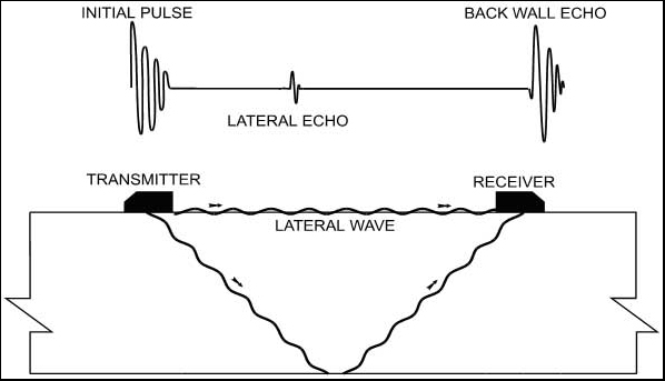
The TOFD system relies not only on the specularly reflected ultrasonic wave but also on the diffracted signal that occurs as a result of wave interaction with any defect which may occur within its path. Unlike conventional ultrasonics the TOFD system does not rely on amplitude in the assessment of defect size by typically the 6 or 20dB drop systems, but relies simply on the time of flight of the returned signals. The system relies on the use of two probes in a pitch and catch arrangement producing a refracted longitudinal wave at angles similar to those used in conventional A-scan systems eg 45-60-70 degrees. In addition a further wave is generated which is transmitted along the tested items surface, directly between the transmitter and receiving probes, referred to as a lateral creeping wave. see Figure. 1 attached. With the configuration shown in Figure. 1, and providing there are no defects within the body of the test piece, then the TOFD scan image will appear as shown in Figure. 2 attached. It can be seen that, for this simple configuration, the first echo at the top of the TOFD scan image is the lateral wave and may be thought of as the top of the test specimen, and the lowest echo is the back wall echo with anything in between resultant from a defect. For the same configuration but assuming the test piece contains a midwall defect, see Figure. 3 attached, then the TOFD image will appear as in Figure. 4 attached. For top surface breaking defects see Figures 5 and 6 and for back wall breaking defects see Figures 7 and 8 attached.
Another TOFD image is shown of a real defect within the root area, but not root connected, in a 72mm thick weld, see Figure 9 attached. NOTE with all previous TOFD scans the direction of probe travel has been across the weld cap ie weld cross section but the scan shown in Figure 9 results from scanning with the ultrasonic probes travelling along the weld and producing an image along the length of the weld. It may also be noticed that the backwall rises at the right of the scan due to internal bore matching as this is adjacent to a circumferential weld.
Findings
A number of ultrasonic surveys have now taken place within AUSTA Energy power stations on longitudinally welded pipe. The surveys, having to be conducted within a narrow time frame, which include both the longitudinal and circumferential welds, took the form of four operators using conventional ultrasonics and the TOFD system following on to retest any area that was found to contain defects that broke the defect recording criteria. The criteria chosen was as prescribed in AS2207-1994 level 1 of table 3,7 ie any defect that displayed a signal that was greater than 20% screen height, with the screen set to display a signal from a 1.5 mm side drilled hole to 80%, was considered for further investigation using the TOFD system. The longitudinal welds were produced using a submerged arc process for the root run and metal inert gas welding (MIG) for the fill and cap runs. As part of the MIG process the electrode feed wire was guided between two offset roller guides which resulted in the feed wire being corrugated see Figure. 10 attached. The weld preparation was that of a narrow “J” and it was felt that any lack of side wall fusion defects may present themselves as near vertical in orientation and prove impossible to size using the conventional A-scan methods. AUSTA Energy, being aware of potential problems with this type of configuration, had conducted some round robin ultrasonic results with a special test piece containing a lack of side wall fusion defect in the past. The results of the round robin tests verified the inadequacy of the manual A-scan in producing accurate assessments of defect sizes.
Testing has revealed that some of the lack of fusion defects, in the longitudinal welds, are showing a characteristic intermittent pattern that appears to be resultant from the method of the corrugated wire feed used during welding, as described earlier in this paper. A number of defects were recommended for monitoring and one of them was revisited approximately eighteen months later. The defect was chosen as it had the classic intermittent characteristic and it was considered that if the defect were to begin to grow then the likely scenario would be that the gaps between the individual defects would connect, possibly even before the overall crack length increased. Another factor for choosing this defect was its proximity to the change of section on the internal wall of the pipe due to internal matching of the bore as it is adjacent to a circumferential weld.
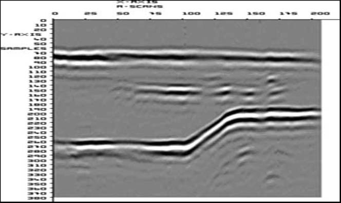
Figure 11, see attached, shows the first TOFD image of the defect and Figure 12, attached, is the second scan of the same defect obtained eighteen months later. There is a difference in the quality of this second scan owing to a couple of factors including a higher frequency probe being used and a change in the design of the probe shoe. The improvements are part of the learning curve as the first scans were produced from the very first survey conducted and we continue to improve our systems and techniques as we gain more experience. One of the differences between the two scans is that the defect shown in Figure. 11, the first scan, may appear to be intermittent on the left side as well as on the right. However observation of the top lateral and backwall wave will show that the apparent intermittency on the left of the defect is a result of loss of ultrasonic coupling. This is proven to be the case as the second scan, Figure. 12, shows, ie the lateral top and back wall waves are continuous. This highlighted feature also demonstrates that the TOFD system, for this type of test, provides the assurance of test integrity by highlighting where coupling has been lost. The conclusion of comparison between the two test results is that the defect remains unchanged.
CONCLUSIONS
The TOFD system has proved an invaluable tool for evaluation of defects and for testing items which have proven too difficult for conventional A-scan techniques.
Whilst its higher cost may still deter some users its economic benefits have been proven to AUSTA Energy who will continue to use it on plant where integrity and accuracy of the results are particularly important. In addition to generator ring testing, welds and rotor bore inspection, AUSTA Energy continues to explore other areas of potential use of their TOFD system.
Whilst not broached earlier in this paper the application of TOFD by technicians with no past experience in conventional ultrasonics is fraught with danger. Another danger, as with many other test systems, is inspecting items with which the test technician is not familiar and has had no previous experience of testing.
Figure. 1 showing both geometry and wave form
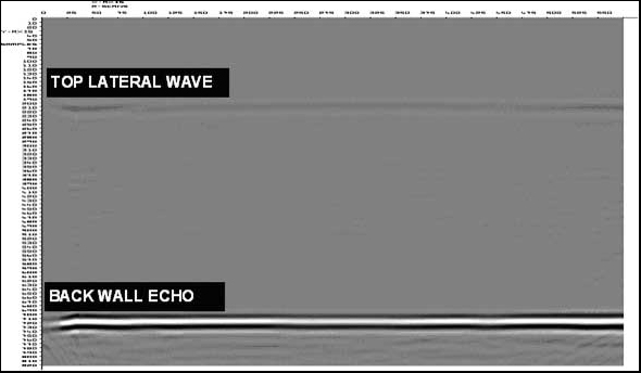
Figure. 2 showing a real TOFD scan with no defects
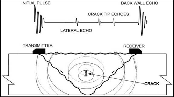
Figure. 3 showing geometry and waveform of a midwall defect. NOTE the distance between the two crack tip echoes represents the through height of the defect.
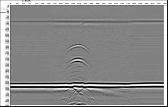
Figure. 4 showing a real TOFD scan of a midwall defect
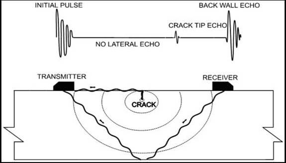
Figure. 5 showing geometry for top surface breaking defect
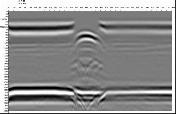
Figure. 6 showing real TOFD scan of a top surface breaking defect
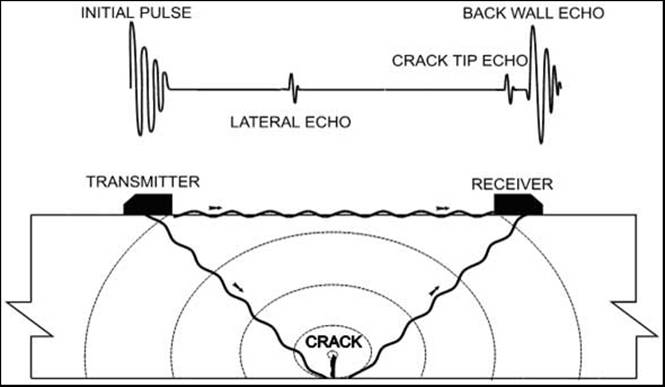
Figure. 7 showing geometry for back wall surface breaking defect
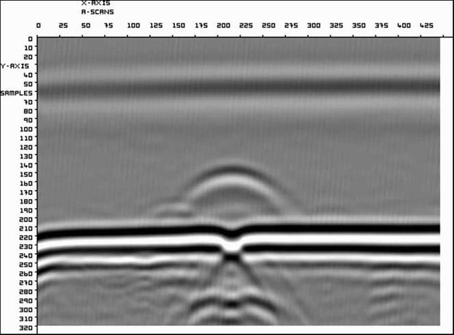
Figure. 8 showing real TOFD scan of a backwall breaking defect
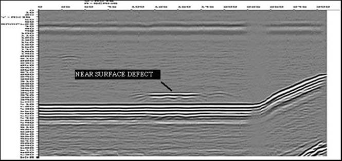
Figure. 9 showing real TOFD scan of weld with near root defect
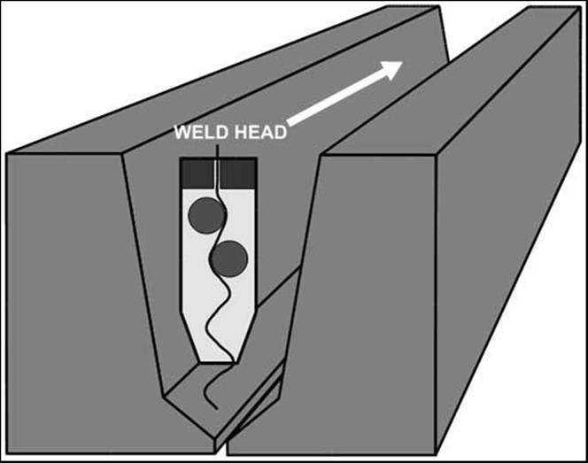
Figure. 10 showing the weld wire feed into the narrow “J” weld preparation, (schematic only)
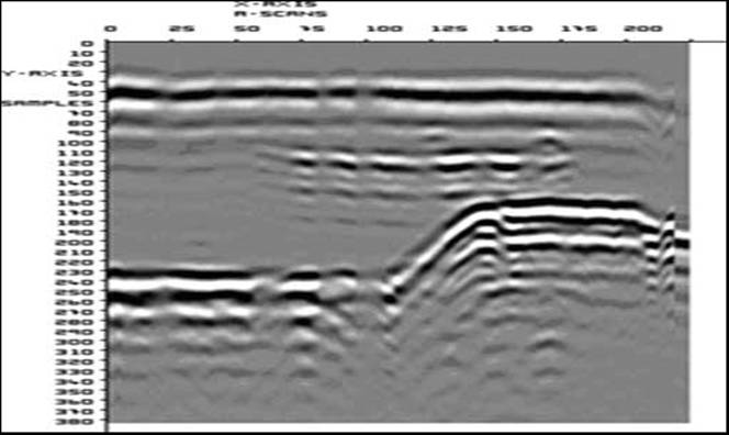
Figure. 11 shows the first TOFD scan on the first survey